
12V Class AB Amplifier using 2SA733 Transistor
Mục Lục
Introduction
In electronic circuits, the amplifiers are very broad in use. Because it converts the weak signal into a strong signal. That’s why used in various circuits. And, we have studied that there are mainly two types of amplifiers. Pre-amplifiers and power amplifiers. Power amplifiers are further classified into different classes. These classes are represented by English letters. The classes include A, B, AB, D, E, F, T, etc. But, the most common in use are Class A, B, AB, and C. So, in this article we are developing the class AB amplifier circuit.
To overcome the cross-over distortions, designers use this class AB amplifier. It uses the intermediate conduction angle of both class A and Class B amplifiers. In the other words, it stands somewhere between both Classes. Thus, more efficient than class A. But, less efficient than Class B amplifiers. Since this amplifier compromises, the linearity and therefore efficiency gets reduced. To power, the circuit uses a 12V DC supply. For the load, use 4 ohms and 20Watt power of the speaker.
Hardware Components
The following components are required to make Class AB Amplifier Circuit
S.NoComponentsValueQty1.PCB Board12.Resistors 6.8k,2.2K,1K,39K,47K,18K,180K,(0.22, 120, 150) Ohms2,1,3,1,1,2,1,
2, 1, 13.Electrolyte Capacitor4.7uF, 100uF, 1000uF, 22pf1, 1, 1, 14.Transistor2SA733,2SD400,2SD313,2SB507,2SB5606, 2, 1, 1, 15.Diode 1N414816.Speaker4-ohm 20watt7.DC supply12V1
2SA733 Pinout
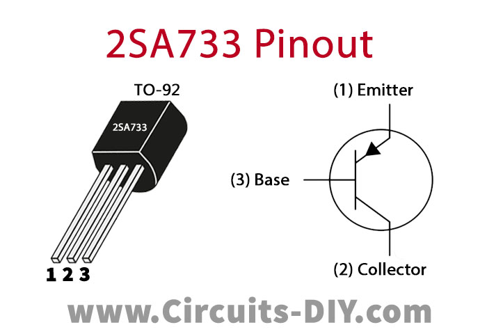
For a detailed description of pinout, dimension features, and specifications download the datasheet of 2SA733
2SB560 Pinout
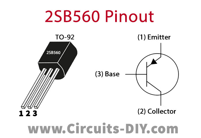
For a detailed description of pinout, dimension features, and specifications download the datasheet of 2SB560
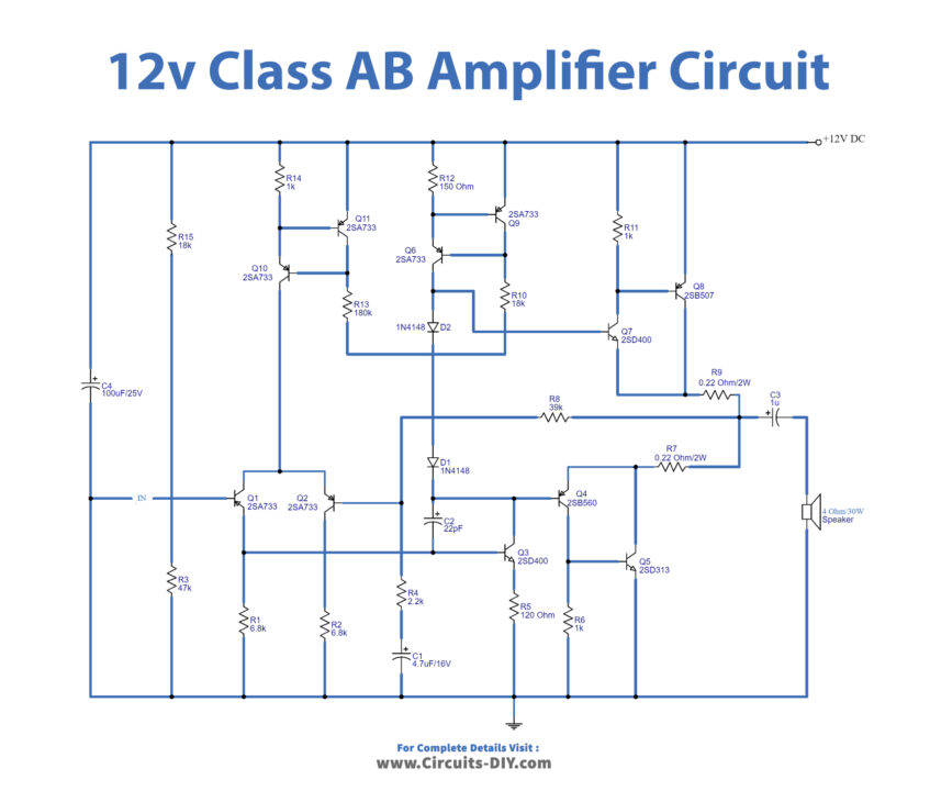
Class AB Amplifier Circuit
Working Explanation
Transistors Q1 and Q2 together make the long-tailed pair. Transistor Q10 and Q11 make a current source for this tailed pair. Transistors Q6 and Q9 form the current source for the second stage of the circuit. R8 is the feedback resistor and it reduces the distinction on the circuit. Q5 and Q8 are the complimentary pairs for the final amplification stage. And, Q4, Q7 is the driving transistor for Q5 and Q8. Capacitor C4 is the power supply capacitor.
Application and Uses
- In Battery operated devices
- In FM radios
- Used to reduce distortion in signals
- In hi-fi systems